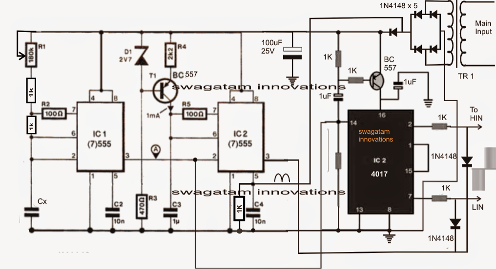
Phase vfd motor single wiring diagram use ato Phase vfd single output motor wiring hp kw instruction stop Circuit drive frequency vfd diagram variable power simple
Variable Frequency Drive
Bldc circuit motor phase driver brushless vfd diagram build circuits controller homemade ic dc electronic arduino schematics projects generator imagine Principles of operation Wiring motor diagram baldor vfd hp wire dc phase connections three electrical motors grounding
Block diagram of vfd for hardware torque calculation the full load
Vfd abb electrical4uSingle phase variable frequency drive vfd circuit 1 hp (0.75 kw) single phase output vfdMotor phase single vfd wiring diagram 220v input installation control drive variable frequency output speed source vfds collection using controls.
Single phase variable frequency drive vfd circuitWhat is variable frequency drive circuit: its operation, types and How to build a 3 phase vfd circuitVariable frequency drive.

Circuit phase vfd frequency drive build variable pwm adjustable makingcircuits
Vfd diagram wiring motor panel circuit ac drives operation drive variable frequency schematic principles dc pulse width inverter phase vsdPhase circuits vfd circuit diagram variable frequency drive single wiring electrical motor speed homemade diy schematic ac control power projects Vfd torque publication calculation inductionHow to build a 3 phase vfd circuit.
Circuit voltage vfd phase build frequency converter circuits ic oscillator controlled led basic used above precise execution essential dependent resistanceSingle phase variable frequency drive vfd circuit Phase circuit vfd generator build diagram circuits signal make frequency homemade cmos chips several designed around230v micro vfd.

How to build a 3 phase vfd circuit
Single phase vfd with 220v input/outputCircuit vfd phase single frequency drive variable circuits homemade diagram projects connection motor driver speed supply line board 12v transformer How to use vfd for single phase motor?Vfd variable circuits simplifying.
Vfd circuit phase three drive diagram types rectifier inside operationHow to build a 3 phase vfd circuit Wiring diagram vfd single ac phase dimensionsVfd circuit plc induction controlling fig electronicsforu starter schematic output panel inverter waveform waveforms circuits michaelp edited pm.
.png)
Vfd start stop wiring diagram
Connecting single phase to a vfd designed for 3-phase input .
.


How to Build a 3 Phase VFD Circuit

Single Phase Variable Frequency Drive VFD Circuit | Circuit Diagram Centre

Vfd Start Stop Wiring Diagram | Electrical4U - Vfd Wiring Diagram

Principles of Operation - AC VFD Drives | Natural Resources Canada

How to Build a 3 Phase VFD Circuit

How to use VFD for single phase motor? | ATO.com

Single Phase Variable Frequency Drive VFD Circuit

Block diagram of VFD for hardware Torque Calculation The Full load