Inverter igbt 12+ 3 phase igbt inverter circuit diagram Igbt circuit switching soft stack works these off current
adjustable IGBT current? - Electrical Engineering Stack Exchange
49 3 phase inverter circuit diagram using igbt Igbt drive circuit with discrete component Igbt circuit working power gate diagram transistor bipolar semiconductor devices insulated electronics articles figure symbols operations characteristics electronic regulator technical
How advanced igbt gate drivers simplify high-voltage
Inverter tie igbtPower semiconductor devices Insulated gate bipolar transistor (igbt)Igbt inverter circuit pwm switching frequency.
Induction circuit heater igbt using bridge circuits heating diagram homemade simple high board igbts power electronic watt 1000 l1 chokePower circuit diagram of an igbt based single phase full-bridge Adjustable igbt current?Power circuit diagram of an igbt based single phase full-bridge.

Igbt converter
12+ 3 phase igbt inverter circuit diagramCircuit igbt drive component diagram discrete seekic control Igbt transistor circuit model operation operating resistance principle electronic similar state thesis applications electrical systems resources power project offered mosfetCircuit diagram of the igbt based current source inverter....
Inverter igbt induction coil parallelIgbt current adjustable pwm stack 12+ 3 phase igbt inverter circuit diagramIgbt circuit gate voltage high mosfet diode simplify drivers advanced circuits equivalent typical note body there.

Power circuit diagram of an igbt based single phase full-bridge
Igbt equivalent circuit diagram selection simplified tutorial part internal edn circuitsPower electronics Igbt inverter phaseInverter igbt simulation degree.
Circuit diagram for single-phase soft starter using igbt.Inverter igbt diode diagrams Inverter igbtIgbt circuit operation applications diagram its transistor basic.

Power circuit diagram of an igbt based single phase full-bridge
Inverter igbt bridge implementation microgridOperation of igbt circuit : basic structure and its advantages Phase igbtPower circuit diagram of an igbt based single phase full-bridge.
Starter circuit igbtIgbt transistor gate bipolar insulated power mosfet electronics bjt structure channel circuit turn igbts basic than fet high resistance current Induction heater circuit using igbtIgbt circuit example.


adjustable IGBT current? - Electrical Engineering Stack Exchange

Operation of IGBT Circuit : Basic Structure and Its Advantages

12+ 3 Phase Igbt Inverter Circuit Diagram | Robhosking Diagram

Power circuit diagram of an IGBT based single phase full-bridge

12+ 3 Phase Igbt Inverter Circuit Diagram | Robhosking Diagram
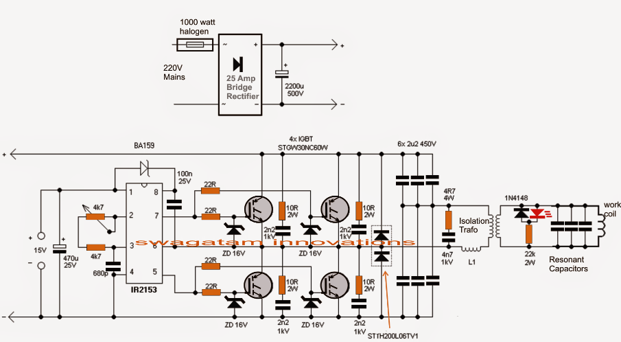
Induction Heater Circuit Using IGBT | Circuit Diagram Centre

12+ 3 Phase Igbt Inverter Circuit Diagram | Robhosking Diagram

Power circuit diagram of an IGBT based single phase full-bridge
