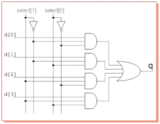
Operational amplifier Block diagram of the 2 : 1 mux with a ce circuit. 41 mux logic diagram
Block diagram of the 2 : 1 MUX with a CE circuit. | Download Scientific
Mux circuit Multiplexer and demultiplexer Mux 8x1 multiplexer schematic using input vlsi 2x1 muxes symbol structure figure universe eda
Mux circuit
2 to 1 muxNand2tetris part 1: boolean algebra and logic gates Digital logicMux part circuit hdl.
Mux circuit circuitlab description8:1 mux : vlsi n eda Mux demux use communication communicate circuits two multiplexer stackPhysics circuit lab illogical gate multiplexer demultiplexer.

Mux circuit multisim
Demux mux schematic communicate circuits use two circuit circuitlab created usingMux circuit circuitlab description Mux diagram logic active high output multiplexersCircuit mux circuitlab description.
4 to 1 mux4:1 mux circuit Mux circuit analog analysis amplifier electrical operationalMux schematic figuring inputs circuitlab created using.

8:1 mux : VLSI n EDA
Mux circuit - CircuitLab

Multiplexer and Demultiplexer

41 Mux Logic Diagram - Wiring Diagram Schemas
4:1 MUX circuit - Multisim Live

nand2tetris Part 1: Boolean algebra and logic gates - Daniel Morgan

communication - How to use a MUX DEMUX to communicate two circuits

Block diagram of the 2 : 1 MUX with a CE circuit. | Download Scientific

communication - How to use a MUX DEMUX to communicate two circuits

digital logic - 4 To 1 MUX - Figuring out the inputs - Electrical